Abstract: Introduce the characteristics of pressure/differential pressure transmitter applied to CIP temperature shock occasions, analyze the impact of transmitter temperature shock in detail, and provide guidance for transmitter selection and application by exploring the transmitter structure design, material selection and principle analysis, and also provide a certain reference for the maturity and development of sanitary transmitter design and manufacturing process.
Key words: CIP cleaning; Induction diaphragm; Transmitters; Temperature sensitive elements; Temperature shock;
CIP (Clean-in-Place) cleaning is a widely used process technology in hygienic industrial production for removing residues, contaminants, and sterilization. The effectiveness of CIP cleaning directly impacts product quality and safety. Typically, the CIP process involves multiple stages: cold water pre-rinsing, high-temperature alkaline solution cleaning, hot water rinsing, high-temperature acid solution cleaning, another hot water rinse, and high-temperature steam sterilization. Each step relies on pressure or differential pressure transmitters to control the injection commands and volumes, demanding extremely high precision from the transmitters. The CIP process operates within a temperature range of 20°C to 120°C, requiring rapid switching between media at different temperatures, which subjects the system to severe instantaneous thermal shocks. Under sudden temperature changes, the transmitter's sensing diaphragm undergoes rapid deformation, leading to increased measurement errors and instability. Since the transmitter determines the injection commands and volumes, inaccuracies can result in operational errors, overfilling, leaks, compromised cleaning effectiveness, and even production quality incidents.
A transmitter comprises a sensing diaphragm, a pressure sensor, fill fluid, and transmitter circuitry. Thermal expansion and contraction of the diaphragm and fill fluid due to medium and ambient temperature fluctuations are normal physical phenomena. However, under abrupt temperature changes, these effects become more pronounced, significantly impacting measurement accuracy. To address this issue, the following three aspects are investigated:
1. Dual Temperature Compensation Design of the Transmitter
Temperature variations induce zero drift in pressure transmitters and alter the temperature sensitivity coefficient, thereby degrading measurement accuracy. Consequently, temperature compensation constitutes an essential procedure in the manufacturing of conventional pressure/differential pressure transmitters. The compensation system utilizes temperature-sensitive elements integrated either on the circuit board or at the pressure/differential pressure sensor to monitor ambient or medium temperatures. A microprocessor collects data at multiple temperature points and implements compensation algorithms to maintain transmitter accuracy across varying temperature ranges. As illustrated in Figures 1 and 2, temperature-sensitive elements are mounted at both the pressure sensor core and the transmitter circuit module. During calibration, a high and low temperature chamber maintains specified temperatures for data collection and algorithm derivation. However, in practical applications, a critical limitation emerges: the physical separation between temperature-sensitive elements and the process medium creates a thermal lag. This discrepancy between actual medium temperature and sensor-detected temperature results in only partial compensation effectiveness. Most significantly, during instantaneous thermal shocks, the temperature-sensitive elements fail to respond promptly to rapid temperature fluctuations. Consequently, the compensation mechanism becomes ineffective, leading to substantially increased transmitter deviations.
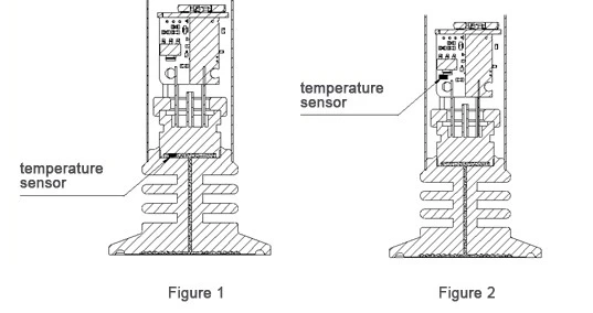
In response to the above technical issues, a dual temperature compensation structure design for transmitters is proposed, which can effectively reduce the measurement errors caused by temperature differences during transmitter measurements. As shown in Figure 3, a temperature element T1 is encapsulated near the liquid-contact medium surface. This allows the temperature of T1 to closely approximate the medium temperature, ensuring real-time monitoring of the medium temperature. Meanwhile, a temperature element T2 is encapsulated near the pressure cup seat. The temperature of T2 is close to the ambient temperature, enabling it to collect the influence of the ambient temperature.

Therefore, the temperature difference can be calculated using the following formula:
▲=T1-T2
During temperature compensation, the rear-end temperature-sensitive element T2 is used to collect temperature data. Since the transmitter compensation is performed in a high-low temperature chamber where T1 and T2 are equal, it can compensate for the influence of constant temperature changes on the transmitter's pressure measurement. When the ambient temperature changes or the medium temperature reaches a steady-state equilibrium (T1 = T2) over a certain period, the temperature compensation effectively minimizes the impact on the transmitter's pressure accuracy. The pressure-transmitting silicone oil expands or contracts with temperature changes. When the pressure-sensing diaphragm is subjected to an instantaneous temperature shock, a temperature difference ▲ occurs between the front-end and rear-end temperature-sensitive elements T1 and T2. Based on the properties of the silicone oil and diaphragm, the relationship between temperature variations and pressure influence can be derived through calculations and experiments, thereby determining the pressure correction value caused by temperature changes. By inputting the temperature difference ▲ data, the corresponding pressure correction value is written into the microprocessor. Through data processing, this effectively resolves the issue of accuracy degradation due to instantaneous temperature shocks. It is important to note that the pressure correction value represents the stress change caused by sudden temperature variations rather than the actual measured pressure. Therefore, correcting this value in the microprocessor program does not compromise the transmitter's accuracy.