I. The Role of Pressure Transmitters in Industrial Automation
Within modern industrial automation and control systems, the pressure transmitter plays an irreplaceable role as the "sensory organ." As one of the most fundamental and widely used measurement instruments in process control, the pressure transmitter is responsible for converting the physical pressure of liquids, gases, or steam in industrial processes into standardized electrical signals that can be recognized by higher-level systems-typically 4-20mA analog signals, or digital communication protocols such as HART, Profibus PA, or Foundation Fieldbus. This seemingly simple conversion from "physical quantity to electrical signal" is actually the critical link that bridges the data gap between the field execution layer and the central control layer. Without accurate and reliable pressure sensing data, any complex PID control loop, interlock protection logic, or advanced process control algorithm would lack a solid foundation.
In terms of industrial application breadth, pressure transmitters cover virtually all precess and discrete manufacturing industries: oil & gas extraction and refining, coal chemical and fine chemical, thermal and nuclear power, municipal water supply and wastewater treatment, food & beverage and biopharmaceuticals, HVAC and refrigeration systems, marine and offshore engineering, and semiconductor cleanrooms. Statistics show that in a typical large-scale petrochemical complex, pressure transmitters account for 30-40% of total instrumentation-their operational stability directly impacts plant availability and safety margins. Therefore, a deep understanding of pressure transmitter technology-from the microscopic mechanisms of sensing elements to the macroscopic architecture of system integration-holds significant engineering value for instrument engineers, automation designers, and maintenance managers alike.
II. Working Principle of Pressure Transmitters
The operation of a pressure transmitter is essentially a multi-stage energy conversion and signal conditioning process. Taking the diffusion silicon pressure transmitter-the most widely used type in the industrial market today-as an example, its complete working chain can be broken down into the following five key steps:
2.1 Pressure Sensing and Mechanical Deformation
When the measured medium (e.g., high-temperature steam, corrosive acids/alkalis, or high-pressure natural gas) enters the transmitter chamber through the pressure inlet, the pressure acts directly on the isolation diaphragm (typically made of 316L stainless steel, Hastelloy C-276, or tantalum, with a thickness of just tens of microns). This diaphragm serves two purposes: it physically isolates the medium from direct contact with the internal sensor chip, and it transmits the external pressure to the internal fill fluid (usually high-purity silicone oil or fluorocarbon oil) for equal hydraulic pressure transmission. This "outer diaphragm + fill fluid + inner diaphragm" structural design enables the transmitter to withstand overload pressures several times the full scale without permanent damage.

2.2 Electrical Characteristic Change of the Sensing Element
The fill fluid transmits the pressure to the MEMS piezoresistive chip (Micro-Electro-Mechanical Systems) at the heart of the sensor. This chip is typically made of monosilicon, with four precision-arranged piezoresistors formed on its surface through microelectronic photolithography, connected in a Wheatstone bridge configuration. When the silicon wafer bends under pressure, the resistors in the tensile zone increase in resistance, while those in the compression zone decrease-this is the well-known piezoresistive effect. Due to the exceptionally high piezoresistive coefficient of monosilicon, even micron-scale deformation causes significant resistance changes (relative change up to hundreds of ppm/kPa), endowing the sensor with extremely high sensitivity.

2.3 Signal Extraction and Primary Amplification
The Wheatstone bridge converts the resistance changes into a differential voltage signal (typically only millivolts in amplitude). This weak signal then enters the preamplifier, where it is amplified through multiple stages by low-noise operational amplifiers to the volt level. At this stage, careful attention must be paid to maintaining a high signal-to-noise ratio-as the raw signal is highly susceptible to electromagnetic interference, thermal noise, and power supply ripple. High-end transmitters employ chopper-stabilized or auto-zero amplifiers to eliminate low-frequency offset and drift.
2.4 Temperature Compensation and Nonlinearity Correction
One of the greatest technical challenges for pressure sensors is temperature drift. The piezoresistive coefficient, elastic modulus, and even geometric dimensions of monosilicon all vary with temperature, causing different output values for the same pressure at different ambient temperatures. To address this, the transmitter incorporates a temperature sensing element (typically a diode or platinum RTD) to monitor the chip temperature in real time. The microprocessor uses pre-stored temperature-pressure calibration data tables to dynamically compensate the output via software algorithms, achieving combined accuracies of ±0.075% FS or better across the full temperature range. Additionally, due to non-ideal mechanical and bridge characteristics, the output signal does not have a perfectly linear relationship with actual pressure-polynomial fitting or piecewise interpolation algorithms are applied for linearization correction.
2.5 Standardized Output and Communication Protocols
The conditioned signal is finally converted to an industry-standard output format. The traditional approach uses 4-20mA two-wire analog output-where 4mA represents zero (lower range limit) and 20mA represents full scale. The advantages of this scheme include: current signals are immune to line resistance, making them suitable for long-distance transmission (up to several kilometers); the 4mA lower current can simultaneously power the transmitter, enabling "signal and power on the same line"; and if the line breaks, the current drops to 0mA, allowing immediate fault detection. Modern smart transmitters add digital communication capability on top of this: HART overlays frequency-shift keying (FSK) signals on the 4-20mA loop for bidirectional digital communication without interference; fully digital protocols like Profibus PA or Foundation Fieldbus eliminate analog signals entirely, transmitting digital data packets directly and supporting multivariable measurement, remote configuration, and diagnostic information upload.
III. Core Structure of Pressure Transmitters
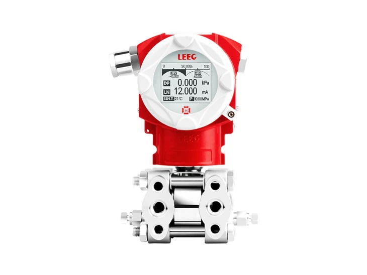
A typical smart pressure transmitter can be divided into four physical modules: the sensor module, electronics module, housing and electrical interface module, and process connection module.
3.1 Sensor Module – The "Heart" of the Transmitter
The sensor module houses the sensing chip and its supporting components as described in Section 2.2. In terms of sensing element technology, the mainstream industrial sensor modules include the following types:
Diffusion Silicon: Piezoresistors are formed by diffusion doping directly on a monosilicon wafer using MEMS technology. Advantages include high sensitivity, fast response, small size, and low batch production costs. Disadvantages are temperature sensitivity and the inherent brittleness of silicon, limiting overload capacity. Suitable for clean fluids and neutral gases in conventional conditions.
Monosilicon Resonant: A micro-machined resonant beam is fabricated on a silicon wafer; pressure changes alter the beam's resonant frequency, and pressure is derived from frequency measurement. These sensors offer extremely high accuracy (up to ±0.04% FS), excellent long-term stability (annual drift < ±0.05% FS), and frequency output with strong anti-interference capability.
Capacitive: Pressure is measured by detecting changes in capacitance between the sensing diaphragm and a fixed electrode under pressure. Capacitive sensors are rugged, have high overload capacity, low temperature drift, and are insensitive to radiation and vibration. The Rosemount 3051 series is a classic representative.
Ceramic Capacitive: High-purity Al₂O₃ or ZrO₂ ceramic serves as both the substrate and diaphragm material, requiring no fill fluid for direct media contact. Ceramic offers exceptional corrosion and abrasion resistance, making it ideal for harsh media such as pulp, slurry, and particle-laden suspensions.
Metal Foil Strain Gauge: Resistive strain gauges are bonded to a metal elastic element; pressure-induced deformation changes the gauge resistance. These sensors are simple and low-cost, but offer lower accuracy and stability-primarily for low-cost general-purpose applications.

3.2 Electronics Module – The "Brain" of the Transmitter
The electronics module typically consists of one or more printed circuit boards (PCBs) integrating the following functional units:
Microcontroller (MCU): The data processing and control core, responsible for A/D conversion, digital filtering, temperature compensation, linearization, range setting, damping adjustment, self-diagnostics, and more. High-performance MCUs also support FFT spectrum analysis and pulsed flow calculation.
A/D Converter: Converts the analog voltage to a digital value-typically 16 to 24-bit resolution with sampling rates up to thousands per second. High-resolution ADC is a prerequisite for high accuracy.
D/A Converter: Converts the digital result back to a 4-20mA analog current output. Some designs use PWM plus low-pass filtering to achieve DAC functionality.
Communication Interface IC: Depending on the protocol, this includes HART modems, RS-485 transceivers, Profibus ASICs, or Ethernet PHYs.
Power Management: Converts the 12-42V DC loop power to the various voltage levels required internally (e.g., 3.3V, 5V, ±15V), with reverse polarity protection, surge suppression, and EMI filtering.
Memory: EEPROM or Flash stores factory calibration data, user configuration parameters, and event logs.
3.3 Housing and Electrical Interface Module – The "Armor"
The housing is typically die-cast aluminum or stainless steel with sealing to achieve specific ingress protection ratings (IP65/IP66/IP67/IP68). For hazardous areas, the housing must comply with explosion-proof (Ex d) or intrinsic safety (Ex ia) design standards to ensure internal sparks cannot ignite external explosive atmospheres. Electrical interfaces include:
Cable entry ports: Standard M20×1.5 or ½" NPT threads, used with explosion-proof cable glands.
Terminal blocks: Typically two-wire terminals (+24V/-Signal), with optional test terminals on some models.
Grounding stud: For connecting shielding and equipotential grounding.
Display: Some models feature an LCD for local reading of pressure values, bar graphs, and alarm status.
3.4 Process Connection Module – The "Sensor Probes"
The process connection interfaces directly with the measured pipe or vessel, including:
Pressure taps: Common specifications include ½" NPT female, G½" male, M20×1.5 male.
Isolation valves and three-valve manifolds: Differential pressure transmitters are typically equipped with three-valve manifolds (balance valve + high/low side shutoff valves) for equalizing pressure before startup, isolating for maintenance, and venting.
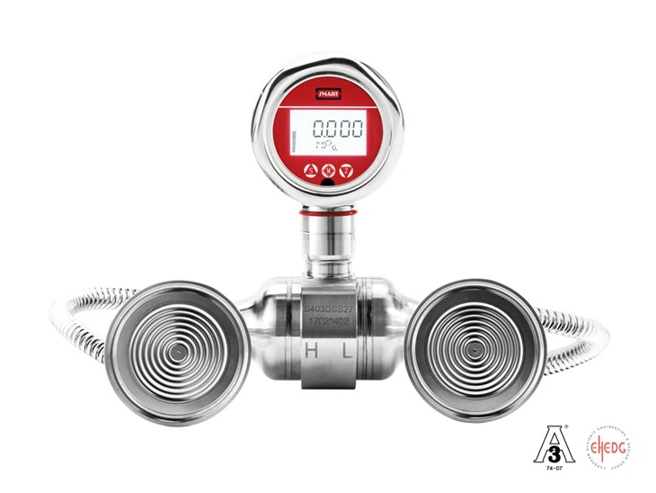
Diaphragm seals: For high-temperature, high-viscosity, crystallizing, or highly corrosive media, remote diaphragm seals (capillary type) are used to transmit pressure through oil-filled capillaries to the transmitter body.
IV. Detailed Interpretation of Key Technical Specifications
Correctly interpreting and understanding pressure transmitter specifications is a prerequisite for scientific selection and proper use. The core parameters are analyzed below:
4.1 Range and Turndown Ratio
Range is defined as the interval between the minimum and maximum pressure values the transmitter can measure-for example, 0-100kPa, -100-200kPa, or absolute vacuum to 35MPa. Turndown Ratio refers to the ratio of the maximum span to the minimum adjustable span. For example, a transmitter with a 100:1 turndown ratio and a maximum span of 10MPa can be adjusted down to a minimum span of 0.1MPa while still maintaining specified accuracy. A high turndown ratio offers greater flexibility, allowing the same transmitter to accommodate multiple process conditions and reducing spare parts inventory. However, note that accuracy typically degrades when the actual span is set well below the maximum span (manufacturers usually specify accuracy at the reference span).
4.2 Accuracy Class
Accuracy is typically expressed as a percentage of full span (%FS), with common classes including ±0.5% FS, ±0.25% FS, ±0.1% FS, ±0.075% FS, and ±0.04% FS. High-accuracy transmitters (better than ±0.1% FS) typically use monosilicon resonant or precision-compensated capacitive technologies. It is important to distinguish between basic error (measured under reference conditions) and combined error (including linearity, hysteresis, repeatability, temperature effects, etc.). For custody transfer or safety interlock applications, products with combined error ≤ ±0.2% FS should be selected.
4.3 Long-Term Stability
This specification measures the output drift relative to the initial calibration value over a specified period (typically one year), expressed as ±0.1% FS/year for example. Long-term stability depends on material aging characteristics, package stress relaxation, and electronic component aging rates. High-quality transmitters use accelerated aging screening and thermal cycling annealing to control annual drift within ±0.05% FS.
4.4 Response Time
The time required for the output signal to reach a specified percentage of the final stable value after a step pressure change-typically 63.2% for the first-order time constant τ, or 90% for response time T₉₀. For general process control, tens to hundreds of milliseconds is sufficient. However, for fast dynamic processes such as compressor surge control or engine test stands, transmitters with response times under 10ms are required, often achieved with special small-volume cavities and high-speed electronics.
4.5 Overload Capacity
The maximum pressure the transmitter can withstand without permanent damage (typically several times the upper range limit, such as 2x, 5x, or even 10x). Overload capacity depends on the mechanical strength of the sensing element and the travel limits of the isolation diaphragm. For applications with potential water hammer or operator errors (e.g., downstream of steam trap valves), products with overload capacity ≥5x should be selected.
4.6 Temperature Effects
Includes zero temperature coefficient and span temperature coefficient, expressed as %/10°C or %/K. For example, a zero temperature coefficient of ±0.02%/10°C means the zero output shifts by no more than 0.02% of full span for every 10°C change in ambient temperature. Temperature compensation ranges are typically -20°C to 80°C (standard) or -40°C to 85°C (wide-temperature). Beyond this range, accuracy degrades significantly.
4.7 Ingress Protection and Explosion Protection Ratings
IP Ratings: IP65 means dust-tight and protected against water jets; IP66 protects against powerful water jets; IP67 allows temporary immersion in 1 meter of water; IP68 allows continuous immersion.
Explosion Protection Markings: Explosion-proof type Ex d IIC T6 Gb (for Zone 1/Zone 2 gas environments, temperature class T6 means surface temperature ≤85°C); Intrinsic safety type Ex ia IIC T4 Ga (for Zone 0). Selection must strictly follow hazardous area classification drawings.
4.8 Media Compatibility
Diaphragm and seal materials in contact with the media must withstand chemical corrosion, abrasion, and temperature. Common material pairings:
Material Application
316L Stainless Steel Most neutral water, oil, gas, and mild acids/alkalis
Hastelloy C-276 Wet chlorine, hypochlorite, concentrated sulfuric acid and other strong oxidizers
Monel 400 Hydrofluoric acid, seawater and other reducing media
Tantalum Fuming sulfuric acid, aqua regia and other ultra-corrosive media
PTFE/PFA Lining Strong acids and alkalis (temperature/pressure limited)
Gold Plating High-purity semiconductor process gases