Differential pressure measurement is indispensable in industrial control processes. Its core is to measure the pressure difference between two different points in the same pipeline, tank, equipment, or process, i.e., the pressure difference between the high-pressure side and the low-pressure side. Compared with single-point pressure measurement, differential pressure measurement not only reflects changes in pressure itself but can also be further used for indirect measurement of parameters such as flow rate, liquid level, filter differential pressure, and equipment operating status. Therefore, it is widely used in industries such as petroleum, natural gas, chemical, power, pharmaceutical, food, metallurgy, and water treatment.
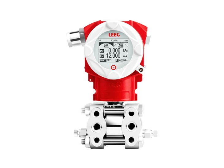
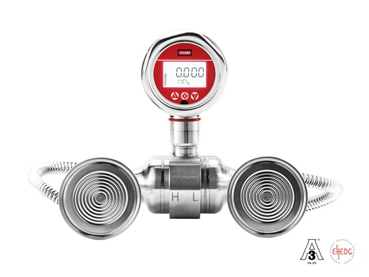
In actual industrial sites, differential pressure is typically detected using a differential pressure transmitter. The transmitter introduces two measured pressures through the high-pressure side (H) and the low-pressure side (L) respectively. After the sensor senses the pressure action on both sides, it converts the pressure difference into an electrical signal. After signal processing, temperature compensation, and linearization calculations, it outputs standard signals such as 4~20mA, HART, RS485/Modbus, providing stable process measurement data for control systems, PLCs, DCS, or data acquisition systems.
The key to differential pressure measurement is not just "measuring two pressures and then subtracting them," but rather comprehensively considering factors such as measurement range, static pressure, temperature, medium density, installation method, impulse piping system, and sensor performance. Especially under operating conditions such as high static pressure, low differential pressure, high temperature, and corrosive media, differential pressure measurement places high demands on the sensor structure, temperature compensation algorithms, and overall installation quality of the instrument.
I. What is Differential Pressure?
1. Basic Concepts of Differential Pressure
Differential Pressure (DP) is the pressure difference between two pressure measurement points, and its basic relationship is:
ΔP = P₁ − P₂
Where:
• ΔP: Differential pressure;
• P₁: High-side pressure;
• P₂: Low-side pressure.

For example, if the inlet pressure of a certain equipment in a pipeline is 0.80MPa and the outlet pressure is 0.65MPa, the differential pressure between the two points is:
ΔP = 0.80 − 0.65 = 0.15MPa
The sign of the differential pressure depends on the definition of the high and low-pressure sides. When the high-side pressure is higher than the low-side pressure, the output is positive differential pressure; conversely, it may manifest as negative differential pressure. Therefore, during the selection and installation of differential pressure transmitters, it is necessary to correctly confirm the correspondence between the H and L interfaces and the process piping.
2. Working Principle of Differential Pressure Measurement
A typical differential pressure transmitter mainly consists of pressure interfaces, isolation diaphragms, sensor core, signal processing circuits, temperature compensation modules, and output circuits.
Process media enter the high-pressure side and low-pressure side of the transmitter respectively. The pressures on both sides act on the sensitive element through the isolation system, causing the sensor to produce physical changes related to the pressure difference. Taking capacitive, piezoresistive, or monocrystalline silicon pressure sensing technologies as examples, the sensor converts this mechanical change into an electrical signal.
After analog-to-digital conversion, digital filtering, temperature compensation, linearization, and calibration, the instrument converts the measured differential pressure into a standard output signal.
For a 4~20mA output differential pressure transmitter, its theoretical output can be expressed as:
I = 4mA + 16mA × (ΔP − ΔPmin) / (ΔPmax − ΔPmin)
For example, if the differential pressure measurement range is 0~100kPa, when the actual differential pressure is 50kPa, the theoretical output is:
I = 4 + 16 × 50/100 = 12mA
Therefore, the control system can deduce the actual differential pressure based on the transmitter's output signal.
3. Difference Between Differential Pressure and Static Pressure
A very important concept in differential pressure measurement is "static pressure."
Assume the high-side pressure is 10MPa and the low-side pressure is 9.9MPa, then:
ΔP = 10 − 9.9 = 0.1MPa
At this point, although the measured differential pressure is only 0.1MPa, the actual static pressure borne by the transmitter may be close to 10MPa.
Therefore, the differential pressure transmitter must not only meet the differential pressure range requirement but also meet the maximum working static pressure requirement.
This is also one of the important differences between differential pressure measurement and ordinary pressure measurement in terms of selection. For high static pressure, low differential pressure applications, if only the differential pressure range is considered while ignoring the static pressure capability, it may cause a significant static pressure influence on the sensor, thereby reducing measurement accuracy.
II. How to Verify Technical Parameters for Differential Pressure
Measurement
The selection of a differential pressure transmitter should not only look at the "range" and "accuracy." In practical applications, it is recommended to systematically verify according to the following parameters.
1. Measurement Range
First, determine the minimum differential pressure, normal differential pressure, and maximum differential pressure that may actually occur in the process system.
For example, the normal pressure drop of a certain filter during operation is about 20kPa, and it may reach 80kPa under clogged conditions. An appropriate differential pressure range can be selected according to process requirements.
If the range is too large, the actual operating point will be in the lower range interval for a long time, affecting the effective measurement resolution; if the range is too small, it may exceed the range under abnormal operating conditions.
2. Static Pressure
Static pressure is a parameter that must be paid special attention to when selecting differential pressure transmitters.
For example:
• Differential pressure range: 0~10kPa
• Pipeline pressure: 4MPa
• Actual differential pressure: 5kPa
At this point, it cannot be simply considered that the instrument only needs to meet the pressure capacity of 10kPa; it is also necessary to confirm that the transmitter can withstand a working static pressure of about 4MPa and check the influence of static pressure on zero point and range.
3. Accuracy
The accuracy of differential pressure transmitters is usually expressed as a percentage of full scale, such as ±0.1%FS, ±0.075%FS, etc.
For a transmitter with a 0~100kPa range and accuracy of ±0.1%FS, the theoretical basic error magnitude is:
100kPa × 0.1% = ±0.1kPa
It should be noted that the actual measurement error may also be affected by factors such as temperature, static pressure, installation position, impulse piping, and long-term stability. Therefore, engineering selection cannot merely compare an "accuracy number."
4. Overload Capacity and Static Pressure Influence
Industrial sites may experience valve misoperation, pressure fluctuations, startup shocks, etc., so it is necessary to confirm the transmitter's single-side overload capacity and maximum static pressure.
Especially in high static pressure differential pressure measurement, attention must also be paid to the zero drift caused by static pressure changes. High-performance differential pressure transmitters usually reduce these effects through sensor structure design and static pressure compensation algorithms.
5. Temperature and Medium Conditions
It is necessary to check the process temperature, ambient temperature, and whether the medium is corrosive, viscous, crystallizing, or contains solid particles.
For high-temperature media, the impact of process temperature on the transmitter can be reduced through condensate pots, cooling fins, or remote seals; for corrosive media, it is necessary to select appropriate diaphragm and wetted materials based on the nature of the medium, such as 316L, Hastelloy, Tantalum, etc.
6. Output and Communication Methods
Common outputs include:
• 4~20mA;
• 4~20mA + HART;
• RS485/Modbus RTU;
• Other digital communication methods.
For traditional DCS and PLC systems, 4~20mA still has high field applicability; for systems requiring remote parameter setting, diagnostics, and maintenance, products with HART communication functionality can be considered.
III. What Are the Applications of Differential Pressure Measurement?
The biggest characteristic of differential pressure measurement is that it can obtain other process parameters through the pressure difference, so its application range far exceeds simple "pressure difference detection."
1. Pipeline Flow Measurement
Differential pressure flow measurement is one of the classic applications in industrial process measurement.
When fluid passes through throttling devices such as orifice plates, nozzles, or Venturi tubes, the fluid velocity changes, creating a pressure difference before and after the throttling device. According to fluid mechanics relationships, there is a certain relationship between flow rate and the square root of the differential pressure:
Q ∝ √ΔP
Under ideal conditions, it can be expressed as:
Q = C√ΔP
Where Q is the flow rate, and C is a comprehensive coefficient related to the nature of the medium, pipeline structure, and throttling device.
Therefore, by measuring the differential pressure before and after the throttling device, the pipeline flow rate can be indirectly calculated.
In actual engineering, factors such as medium density, temperature, pressure, Reynolds number, throttling device structure, and installation conditions also need to be considered. Therefore, high-precision flow measurement usually requires compensation of related parameters.
2. Liquid Level Measurement
Differential pressure transmitters can also be used to measure tank liquid levels using the pressure generated by the liquid column.
The basic relationship for liquid column pressure is:
ΔP = ρgh
Where:
• ρ is the liquid density;
• g is the acceleration due to gravity;
• h is the liquid level height.
Therefore, when the density is relatively stable, the liquid level can be calculated by measuring the differential pressure generated by the liquid column.
For open tanks, the liquid level can usually be measured using the relationship between the pressure at the bottom of the tank and atmospheric pressure; for closed tanks, the gas phase pressure at the top of the tank must also be considered, so a differential pressure transmitter is usually used to connect to the bottom and top of the tank respectively.
In tanks with high temperature, high vacuum, or volatile media, factors such as condensate, density changes, and remote seals need further consideration.
3. Filter Differential Pressure Monitoring
During normal filter operation, the filter medium produces a certain pressure loss. As the filter element gradually clogs, the pressure difference between the front and back will continuously increase.
Therefore, pressure taps can be installed at the filter inlet and outlet respectively to monitor in real-time through a differential pressure transmitter:
ΔP = P_inlet − P_outlet
When the differential pressure reaches the set value, the control system can issue an alarm to remind maintenance personnel to check or replace the filter element.
This method is widely used in air filtration, liquid filtration, oil and gas processing, and industrial dust removal systems.
4. Pump, Fan, and Compressor Operation Monitoring
In equipment such as pumps, fans, and compressors, the inlet-outlet differential pressure can serve as one of the important parameters for judging equipment operating status.
For example, monitoring the pressure difference between the pump inlet and outlet can assist in judging the pump's operating condition; in gas conveying systems, changes in the differential pressure before and after fans or compressors can also be used for operating status monitoring.
It should be noted that equipment differential pressure cannot represent the equipment's health status alone. In engineering applications, it is usually necessary to combine parameters such as flow rate, temperature, vibration, and current for comprehensive judgment.
5. Clean Systems and Ventilation Systems
In clean rooms, laboratories, pharmaceutical workshops, and air handling systems, a certain pressure gradient needs to be maintained between different areas.
By using differential pressure transmitters to measure the pressure difference between two areas, it can be determined whether the clean area is maintained at the specified pressure state.
For example, in clean areas that need to maintain positive pressure, the pressure difference between the room and adjacent areas can be monitored; in some places requiring negative pressure control, the differential pressure signal can be used to judge the negative pressure state.
6. Airtightness and Leak Detection
In fields such as precision manufacturing, automotive parts, valve fittings, and medical devices, differential pressure measurement can also be used for airtightness testing.
During the testing process, a certain pressure of test gas is charged into the test object, and by monitoring the pressure change before and after the test, it can be determined whether the test object has leaks.
For low differential pressure and micro-leakage detection, higher requirements are usually placed on the differential pressure sensor's resolution, stability, temperature compensation, and response speed.

IV. Key Engineering Issues in Differential Pressure Measurement
Differential pressure measurement may seem simple, but there are multiple influencing factors in actual engineering applications.
First is the impulse piping system. The length, inner diameter, installation height of the impulse lines, and whether there are air bubbles, liquid accumulation, or particle deposition inside the lines may affect the measurement results. For liquid media, it is necessary to avoid gas from entering the impulse lines; for gas media, it is necessary to avoid condensate accumulation.
Second is the installation method. The high and low-pressure sides of the differential pressure transmitter must be correctly connected to the process piping, and a reasonable pressure tapping position should be selected based on the medium state. For media such as high-temperature steam, it is also necessary to use condensate to form a liquid seal to prevent the high-temperature medium from directly entering the transmitter.
Third is the temperature effect. The sensor itself has temperature characteristics, and changes in medium temperature may also cause density changes. Therefore, high-precision differential pressure measurement usually requires temperature compensation, and some flow and liquid level applications further require density compensation.
In addition, for high static pressure, low differential pressure applications, special attention must be paid to static pressure influence, overload capacity, and zero-point stability. For example, when measuring a small differential pressure of a few kPa under pipeline pressures of several MPa or even higher, the sensor must not only withstand high static pressure but also accurately resolve very small differential pressure changes, which places higher demands on the sensor structure and signal processing technology.
V. Summary
The essence of differential pressure measurement is to accurately obtain the pressure difference between two pressure points, with the basic formula being ΔP=P₁−P₂. Through this fundamental parameter, measurements of various industrial parameters such as flow rate, liquid level, filter differential pressure, equipment operating status, and airtightness can be further realized.
In actual engineering, the selection of differential pressure transmitters should not only focus on the measurement range and accuracy but also comprehensively consider static pressure, overload capacity, static pressure influence, temperature range, medium characteristics, wetted materials, impulse line method, output signal, and installation conditions.
With the continuous development of industrial automation and process control systems, differential pressure measurement is evolving from traditional single-parameter detection towards high precision, digitalization, and intelligent diagnostics. For complex industrial operating conditions, sensor technology, temperature compensation, static pressure compensation, and digital signal processing capabilities will directly affect the long-term stability and practical application effectiveness of the differential pressure measurement system.