As a critical measurement device in the field of industrial automation, the performance reliability of level transmitters directly impacts production safety and efficiency. To ensure the sealing performance of level transmitters meets standards, high-precision leak detection systems are required for rigorous testing. This article elaborates on the design principles, structural composition, and key technologies of the test fixture for the leak detection system. It focuses on analyzing the application of differential pressure transmitters in leak detection, the mechanical performance and sealing design of the fixture, and the influence of machining accuracy on test results, providing a comprehensive solution for quality control of level transmitters.
4 Leak Detection System Principle
4.1 Leak Detection System Principle
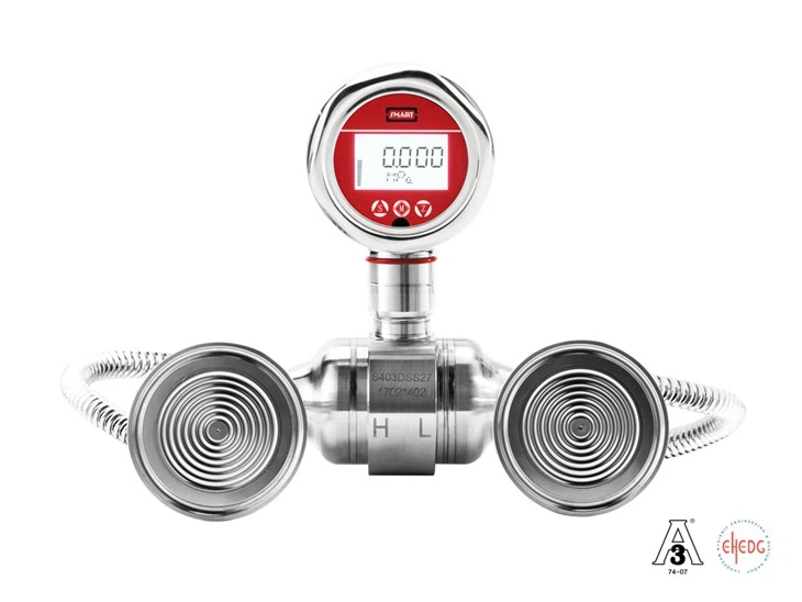
The leak detection system is designed based on a high-precision differential pressure transmitter, connecting the test piece and the reference chamber to the high and low-pressure ends of the transmitter, respectively. First, both ends are pressurized simultaneously and maintained for a period to achieve pressure equilibrium. Then, valves are used to isolate them into two independent chambers. By detecting the pressure difference between the two chambers, the system accurately determines whether the workpiece has leaks.
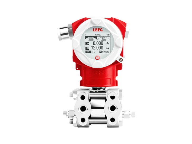
The differential pressure transmitter used in this system is a mon-silicon piezoresistive type. When the measured pressures P1 and P2 act on the isolation diaphragms at the high and low-pressure ends respectively, the pressure is transmitted to the silicon sensing element via silicone oil. Under differential pressure, the silicon element deforms, causing resistance changes, from which the differential pressure value is obtained.
When using compressed air as the test medium, it must first undergo filtration and drying to minimize the impact of temperature variations and compression deformation on pressure measurement. Additionally, the pressure should be adjusted to a range suitable for the level transmitter's measurement range to avoid product damage due to excessive pressure. Inlet ball valve A, isolation ball valve B, and exhaust ball valve C must all be high-precision products, as leakage in the valves themselves can directly cause the entire leak detection system to fail. Furthermore, the differential pressure transmitter should have display and output functions to show real-time pressure changes in the two chambers and preset alarm functionality to trigger an alert when the differential pressure reaches the set value.
4.2 Leak Detection System Structure

5 Test Fixture Design
5.1 Fixture Force Analysis
In mechanical design, while meeting the predetermined functional requirements, it is essential to pursue excellent performance, high efficiency, and low cost, ensuring the equipment is safe, reliable, easy to operate and maintain, and aesthetically pleasing throughout its service life.
When a mechanical fixture fails to function properly, it is considered a failure. The causes of failure include fracture, plastic deformation, elastic deformation, excessive wear, loose connections, frictional slippage, etc., which primarily involve strength, stiffness, wear resistance, stability, and temperature effects.
When designing the test fixture for level transmitters, since it is a static connection, the primary consideration is the fixture's pressure-bearing capacity, with a focus on strength and stiffness in the design. This test fixture adopts a five-station operation mode, so the pressing force of the five-station top plate must first meet the requirements. Calculations show that the force on a single level transmitter is Fb = P×S = 2×10⁵×6.155×10⁻⁴ = 123N, and the pressing force of the five-station top plate is Fa = 5×Fb = 615N. This means the static load borne by the pressing plate must exceed 615N.
5.2 Sealing Method Analysis
Sealing methods are mainly divided into static sealing and dynamic sealing. Since this test fixture is only used for leak detection of level transmitters and involves no reciprocating motion, it falls under static sealing. Static sealing can be further categorized into cylindrical static sealing and planar static sealing. The leakage gap in cylindrical static sealing is radial, while in planar static sealing, it is axial. To facilitate product replacement during testing, the fixture adopts cylindrical static sealing and uses O-rings as the sealing element.
When selecting O-rings, the compression ratio and stretch rate must be carefully considered. The proper fit between the O-ring and the sealing groove dimensions is crucial for achieving appropriate compression and stretch rates, which directly affect sealing performance and service life. Generally, the compression ratio W for cylindrical static sealing ranges from 10% to 15%, while for planar static sealing, it ranges from 15% to 30%. The stretch rate typically ranges from 1% to 5%. The compression ratio W is calculated as W = (d0 - h)/d0 × 100% (where d0 is the cross-sectional diameter of the O-ring in its free state, and h is the distance between the groove bottom and the sealed surface, i.e., the compressed cross-sectional height). The stretch rate a is calculated as a = (d + d0)/(d1 + d0) (where d is the shaft diameter, and d1 is the inner diameter of the O-ring).
5.3 Machining Accuracy Analysis
The gap sealing method using O-rings imposes extremely high requirements on the machining accuracy of the shaft hole and sealing groove. The analysis focuses on the following three aspects:
- Dimensional Tolerance: The shaft hole and shaft adopt a clearance fit. If the dimensions are too small, the shaft cannot be smoothly inserted into the hole. If the dimensions are too large, the improper gap can lead to sealing failure under pressure. The fit between the sealing groove and the O-ring is equally critical. If the groove is too large, the O-ring cannot function effectively; if it is too small, the O-ring may be excessively compressed, leading to damage or assembly difficulties.
- Geometric Tolerance: If the concentricity tolerance of the shaft hole and sealing groove does not meet standards, the O-ring will be unevenly compressed, resulting in localized sealing failure or potential leakage risks.
- Surface Roughness: During machining, the smaller the tool marks on the surfaces of the shaft hole and sealing groove, the higher the surface roughness accuracy. This ensures tighter contact between the O-ring and the surface, improving sealing reliability.
This article systematically discusses the design key points of the level transmitter leak detection system through a combination of theoretical calculations and engineering practices. From the selection of the differential pressure transmitter to the optimization of the fixture's sealing structure, the design philosophy emphasizes high precision and high reliability. In the future, with the advancement of industrial intelligence, leak detection technology for level transmitters will further integrate real-time monitoring and data analysis functions, providing more efficient safeguards for the safe operation of industrial equipment.