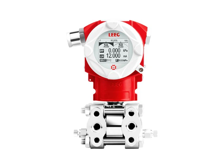
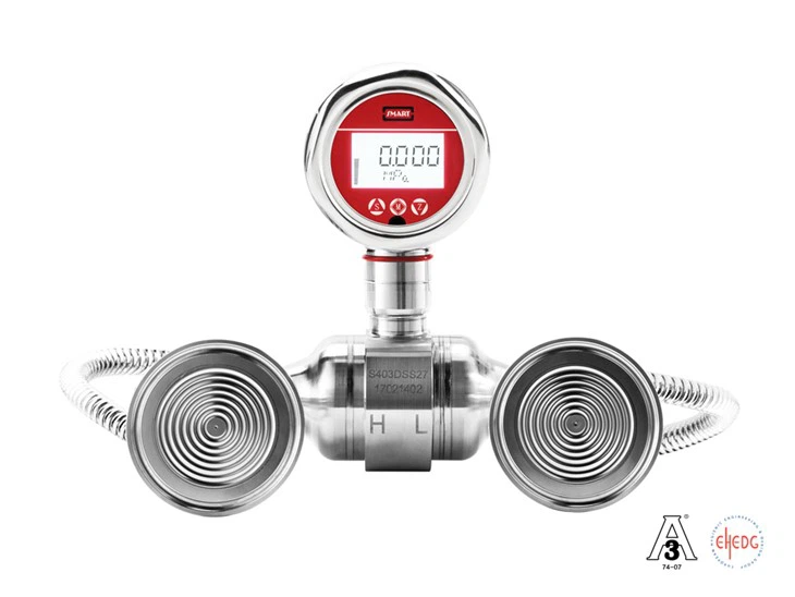
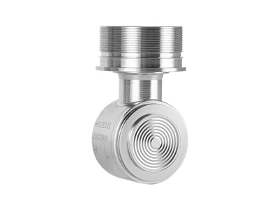
Hygienic pressure transmitter design is a core principle in ensuring product safety and quality in process industries such as food, beverage, and pharmaceuticals. Its core goal is to eliminate corners in equipment that can harbor microorganisms, harbor contaminants, or be difficult to clean through careful design and manufacturing. For transmitter surfaces that come into direct contact with the processed product, their design, processing, and treatment directly determine the effectiveness and efficiency of cleaning and serve as a critical barrier to preventing secondary contamination.
3. Hygienic Design of Contact Surfaces
3.1 Surface Roughness
A key aspect of hygienic design is whether the product meets the cleaning requirements of various production sites. During the production and processing process, residues inevitably adhere to the transmitter surface due to the influence of ambient temperature and the product's inherent properties. If not cleaned promptly, secondary contamination can occur. According to the 3-A sanitary standard, the contact surface roughness Ra should be at least 0.8 μm. Transmitter contact surface roughness is typically controlled through machining equipment, but can also be achieved through surface treatments such as mechanical polishing, electrolytic polishing, and oxidation treatment. While ensuring consistent production processes, dedicated roughness testing equipment must be used for process control of contact surface roughness.
3.2 Welding
Transmitters typically use welding to connect and install pressure-sensing diaphragms, package connectors, and other components. The quality of the welding process is a key component of hygienic design. First, welding must be continuous; feed welding is generally not permitted. If feed welding is necessary, the solder material must meet hygienic requirements. Second, the weld surface must be smooth and uniform, without any dents, wrinkles, cracks, or fissures.
3.3 Sealing
Transmitters are typically sealed using gaskets, O-rings, or hard seals. The sealing material must be in contact with the product being measured and prevent leakage. Gasket seals must be removable or adhesive-bonded to facilitate cleaning and replacement in various applications. The depth of the gasket groove should be less than its width. For removable gaskets with a cross-sectional area greater than 1/4 inch, the groove should not exceed 1/4 inch in depth or be less than 1/4 inch in width. According to the 3-A sanitary standard, seals with a cross-sectional area ≤ 1/4 inch must also meet the relevant requirements. In O-ring and hard seal designs, the contact line of the O-ring and hard seal should be roughly flush with the installation contact surface, so that part of the surface of the O-ring or hard seal contact line is exposed to the cleaning medium, which is easy to clean and does not harbor dirt (as shown in the following figures respectively).


3.4 Minimum Design Radius
When designing transmitter angles, avoid sharp corners as much as possible. Instead, ensure they are seamless, drainable, and cleanable. According to 3-A sanitary standards, angles less than 135° must be rounded, with a radius of 1/8 inch or greater. Where this requirement is unattainable, the radius should be at least 1/32 inch. To prevent damage, when the sensing diaphragm is embedded more than 1/32 inch into the fitting surface, the radius should be greater than or equal to the embedment depth. No radius is required when the embedment depth is less than 1/32 inch. In seal groove design, when the seal cross-section is 1/4 inch or greater, the minimum corner radius of the retaining groove should be 3/32 inch. For cross-sections less than 1/4 inch, refer to the following figure.

For non-standard circular, square, rectangular, or other shapes, if the cross-sectional dimension is less than 1/4 inch, refer to Table 1. There is no minimum fillet radius requirement for flat seals and product contact joints. The width, depth, and minimum fillet radius requirements do not apply to bonded gasket retaining grooves. At the 90° position of machined components, if the minimum fillet radius requirements cannot be achieved due to factors such as space limitations, material thickness, gasket interference within the fitting, etc., a pair of 135° angles can be substituted. However, it must be ensured that the distance between the two 135° angles ("A" in the figure below) is not less than 1/32 inch.

In summary, the design of sanitary pressure transmitters for contact surfaces is a systematic project, encompassing multiple interrelated dimensions, including surface roughness, welding, sealing, and fillet radius. Strict adherence to 3-A and other sanitary standards is the cornerstone for ensuring equipment cleanliness from the source, achieving effective cleaning and sterilization, and ultimately ensuring process safety and product quality. With technological advancements and increasing industry requirements, the concepts and standards of sanitary design will continue to evolve, driving both equipment manufacturers and end users to pursue higher levels of hygiene.