What installation methods are available for pressure transmitters on atmospheric open tanks, and what scenarios does each suit?
Level measurement in atmospheric open tanks is essentially hydrostatic pressure measurement: the pressure generated by the liquid column is proportional to the liquid level height. There are three common installation methods.
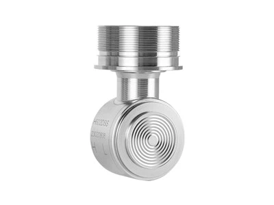
Bottom mounting installs the transmitter at the bottom of the tank or on the side near the bottom, with the pressure port connected directly to the medium inside the tank. This offers the shortest pressure transmission path and the fastest response, making it suitable for clean, low-viscosity liquid media.
Top mounting is suitable for scenarios where opening a hole at the tank bottom is undesirable or where the transmitter must be isolated from corrosive media; it requires a rod-type or cable-type probe to conduct pressure.
Cable-type external tank mounting is typically used when the tank is already in service and cannot be drilled or is difficult to access for maintenance; the measuring assembly is installed outside the tank and connected to the tank bottom via a communicating pipe. The core considerations in these methods are liquid properties, tank structure, measuring range, and maintenance requirements.
For top mounting on an open tank, how do you choose between rod-type and cable-type probes, and what should be noted during installation?
Rod-type probes are suitable for relatively short measuring ranges and media with good flowability. The probe tip should maintain a gap of at least 50 mm from the tank bottom to avoid contact that could cause mechanical stress or measurement errors. Cable-type probes are used for large ranges or deep tanks. Their flexible structure allows the probe to bend appropriately with the tank shape, but installation must ensure that the cable does not contact the tank wall, internal supports, or agitators. The design of the mounting nozzle is equally critical: the nozzle bore should preferably be DN50 to DN150, and its height should be kept within 150 mm. An excessively long nozzle creates a localized dead zone around the probe, leading to measurement lag or false echoes.

What special requirements apply to cable-type external tank mounting?
Cable-type external tank mounting imposes strict requirements on the slope of the communicating pipe, typically requiring an inclination of no less than 1:10 to ensure the pipe is filled with medium and free of accumulated bubbles. If the slope is insufficient, air pockets easily form in the communicating pipe, causing the measured value to read low or fluctuate. In addition, the communicating pipe should be as short and straight as possible, with a minimum number of elbows, to avoid blockage and response lag.
Why must differential pressure measurement be used for level measurement in pressurized closed tanks?
The gas-phase pressure inside a closed tank is not atmospheric pressure. If only a single gauge pressure transmitter is used to measure the pressure at the tank bottom, the measured value includes the gas-phase pressure and cannot independently reflect the hydrostatic pressure of the liquid column. Therefore, differential pressure measurement must be used: the high-pressure side of the transmitter connects to the liquid-phase pressure tap at the tank bottom, and the low-pressure side connects to the gas-phase space. The measured differential pressure is the hydrostatic pressure of the liquid column, from which the level height can be derived.
What are the key requirements for installing differential pressure impulse lines?
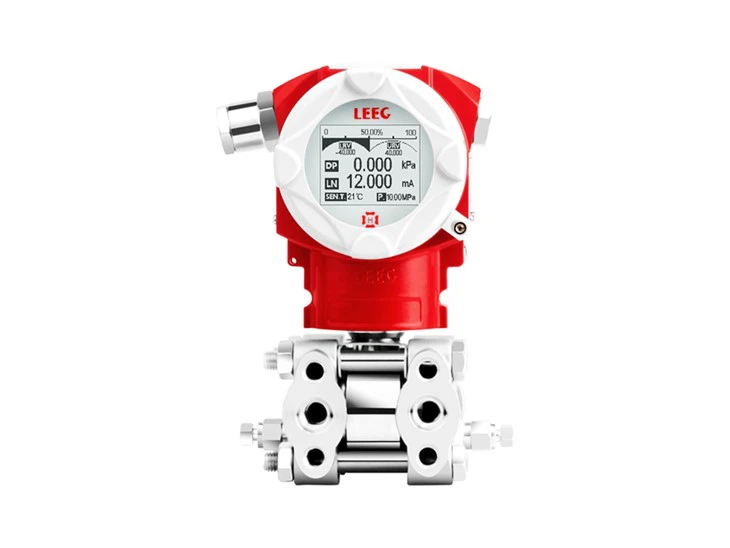
The high-pressure side impulse line is led out from the lower part of the tank, and the low-pressure side from the gas-phase space at the top of the tank. The two lines connect to the high- and low-pressure ports of the transmitter respectively. The core challenge lies in controlling the fluid state within the impulse lines. Horizontal impulse lines must be installed with a slope: when measuring liquids, slope downward toward the transmitter; when measuring gases, slope upward. The slope should be at least 83 mm/m (approximately 1:12). The purpose of this requirement is to ensure that condensate or gas in the lines can drain naturally in the intended direction, avoiding additional hydrostatic errors caused by liquid columns or gas columns forming in the lines. For steam media, a condensate water seal should be maintained in the impulse lines, and the transmitter should be installed below the pressure tap so that condensate can flow back naturally.

Under what circumstances should differential pressure capillaries be used instead of impulse lines?
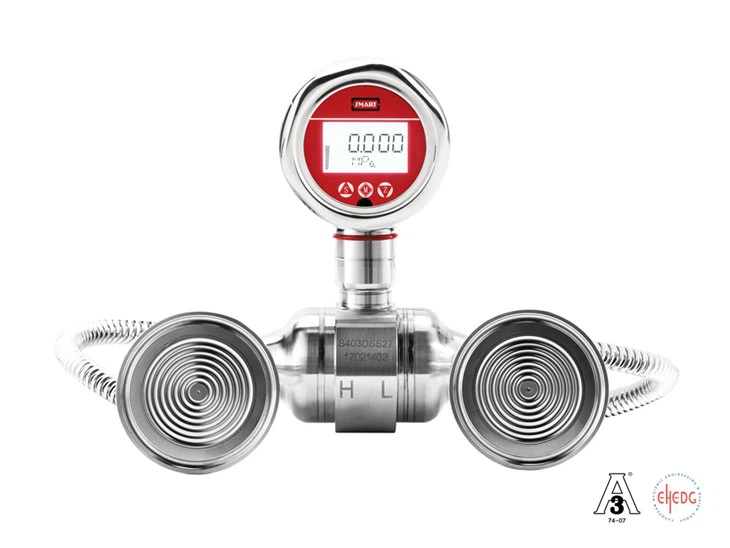
When the medium is viscous, prone to crystallization, highly corrosive, or prone to freezing, the impulse line solution faces risks of blockage, corrosion, and freezing. In such cases, differential pressure capillaries should be selected. Capillaries use remote seals filled with silicone oil or another pressure-transfer fluid to replace impulse lines, transmitting pressure from the pressure tap to the transmitter diaphragm and eliminating the corrosion risk of the medium directly contacting the transmitter.
What precautions apply to the installation of differential pressure capillaries?
The bending radius of the capillary must not be less than 300 mm. Excessive bending can obstruct the flow of the pressure-transfer fluid and prolong the system response time. The capillary must never be used as a load-bearing component when handling the assembly; mechanical damage from improper handling can cause pressure-transfer fluid leakage. The capillary should be securely fastened to avoid fatigue damage from vibration. When a height difference exists between the transmitter installation position and the pressure tap, the static head of the pressure-transfer fluid in the capillary introduces an additional zero offset. This offset must be eliminated through zero compensation before the transmitter is placed into service.
How should the process diaphragm be protected during installation?
The process diaphragm is the most vulnerable part of the transmitter, with a thickness typically on the order of a few tenths of a millimeter. Any contact with a hard or sharp object during installation can cause irreversible indentation or perforation, resulting in permanent transmitter failure. Burrs at the pressure tap should be carefully removed before installation. When connecting impulse lines, fibrous materials such as hemp should not be used as sealing fillers, as fibers can wrap around the diaphragm. When measuring steam or high-temperature media, the temperature should be reduced to the transmitter's allowable range through impulse lines or heat sinks. Direct exposure of the diaphragm to high-temperature steam should be avoided.
Why should electrical wiring be installed facing downward?
The electrical housing of a transmitter typically has a certain degree of ingress protection, but the cable entry holes and cable entries are the main pathways for moisture intrusion. Installing the electrical connection port facing downward allows the cable to form a drip loop, so rain or condensate runs down the cable sheath and drips off rather than backing up into the housing. Cable entry holes should be sealed with sealant or dedicated sealing fittings. In outdoor or humid environments, this measure directly affects the long-term reliability of the transmitter.


Why does zero offset occur after the transmitter is installed?
Transmitters are typically calibrated at the factory in a specific installation orientation, with the zero reference corresponding to the force balance of the diaphragm in a horizontal state. However, during field installation, the transmitter's mounting orientation often differs from its factory calibration orientation. For gauge pressure transmitters, when the plane of the diaphragm deviates from the vertical state, the gravitational component acting on the internal movable parts of the sensor changes, producing a small zero offset. For differential pressure transmitters with capillary systems, the effect of installation orientation is more pronounced: the static head of the pressure-transfer liquid in the capillary is directly superimposed on the differential pressure signal. For every 1 meter change in height difference between the transmitter and the pressure tap, an additional bias of approximately 0.1 bar is produced for a silicone oil fill fluid with a density of about 1 g/cm³.

Under what conditions should zero compensation be performed?
Zero compensation should be performed after the transmitter has been mechanically installed and the impulse lines are filled with medium but before process pressure is introduced (or with the high- and low-pressure sides balanced). For gauge pressure transmitters, ensure the diaphragm is open to atmosphere. For differential pressure transmitters, open the equalizing valve to connect the high- and low-pressure sides, or confirm that the liquid levels in both impulse lines are at the same height. Using a handheld communicator or the transmitter's local zero adjustment function, calibrate the current output to the zero value corresponding to 4 mA.
Can zero compensation replace full-span calibration?
No. Zero compensation can only eliminate a constant bias. It corrects the output deviation of the transmitter at zero pressure but does not change the slope of the sensor's characteristic curve. Therefore, for applications with high accuracy requirements, the lower range value (LRV) adjustment should also be performed after installation, rather than merely pressing the zero button. A complete post-installation verification should also include leakage checks of the impulse lines and response testing: apply a known pressure and observe whether the transmitter output responds linearly and whether the return hysteresis is consistent.
Do absolute pressure transmitters require zero compensation?
The zero point of an absolute pressure transmitter is referenced to absolute vacuum. Since a reproducible absolute-vacuum reference cannot normally be established in the field, conventional zero adjustment should not be performed. If correction for installation orientation effects is needed, lower range value (LRV) adjustment function should be used to compensate at a known reference pressure.
What does the complete post-installation acceptance and verification (PAQ) process include?
The complete PAQ process includes: confirming that the mechanical installation is secure, the impulse line slopes are correct, and there are no leaks; confirming that electrical wiring faces downward and is properly sealed; performing zero compensation under zero pressure or balanced high- and low-pressure conditions; applying a known pressure for response testing to check linearity and return hysteresis consistency; and for differential pressure systems, confirming that the pressure-transfer medium in the capillaries or impulse lines is in normal condition. Together, these steps ensure a smooth transition of the transmitter from "factory calibration state" to "field measurement state."
The installation of a pressure transmitter is a systematic task spanning mechanical, fluid, and electrical aspects. From bottom mounting and top-mounted rod-type or cable-type installation on atmospheric open tanks, to differential pressure impulse line and capillary solutions for pressurized closed tanks, each installation method has its applicable operating boundaries and mandatory operating procedures. The protection of the process diaphragm and the downward orientation of electrical wiring-these seemingly minor requirements often determine whether the transmitter can maintain reliable operation throughout a service life of years or even more than a decade. Post-installation zero compensation is a key step that bridges the "factory calibration condition" and the " actual field installation condition"-it corrects the constant bias caused by installation orientation and the static head of the pressure-transfer fluid, but it cannot replace full-span calibration and complete post-installation verification. Ultimately, the measurement accuracy of a pressure transmitter depends not only on the performance of the sensor itself but also on whether the installation process is rigorous and the verification procedure is complete. Only when every detail is properly addressed during installation can the transmitter continue to output trustworthy data in subsequent operation.