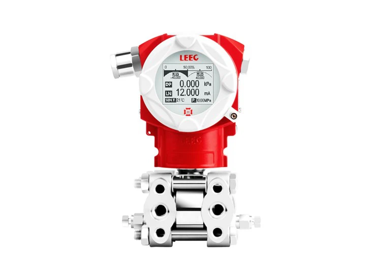
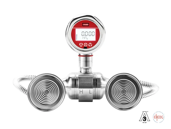
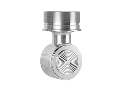
Abstract: This paper introduces the application characteristics of the remote diaphragm differential pressure transmitter, analyzes its structure and function in detail, and explores the structural design and manufacturing process of each component to avoid misunderstandings on model selection which may cause problems during usage. It also provides a reference for developing and expanding the design and manufacturing of domestic process industry instruments.
Keywords: remote diaphragm differential pressure transmitter; process connection; capillary; filling fluid; measuring diaphragm.
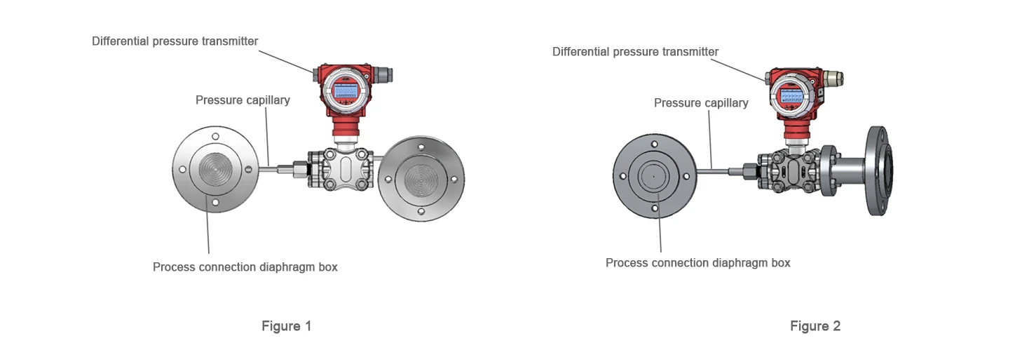
The measurement principle of the remote diaphragm differential pressure transmitter is the same as that of the traditional differential pressure sensor. It also conducts the differential pressure measured by the pressure-sensitive diaphragm to the sensitive element. The difference is that the remote diaphragm differential pressure transmitter adds a pressure-conducting capillary and a process connection diaphragm box, which effectively extends the measurement point, suitable for various installation sites, and with a wider application range.
Remote diaphragm differential pressure transmitters are often used in the following fileds: the medium is corrosive; high process temperature; the medium trends to solidify or crystallization; the medium is high viscosity or with suspended solids, which may cause blockage of the pressure hole; or there is sanitation requirements on the container or pipeline.
1 Structure of the remote diaphragm differential pressure transmitter
The remote diaphragm differential pressure transmitter consists of a differential pressure transmitter and a capillary connected to process connection diaphragm box. Figure 1 and Figure 2 are symmetrical and asymmetrical types remote diaphragm differential pressure transmitters.
2 Design for process connection diaphragm box
What is process connection? Process connection is the installation connection method between measuring instruments and industrial applications, also called instrument joint. Commonly used process connections are threaded connection, flange connection, welding and other methods. Remote diaphragm differential pressure transmitters usually use flange connection, and the flange specifications and dimensions must comply with national standards or industry standards of various countries. Common standards include American standards (ASME B16.5-2003), German standards (DIN 2503), Japanese standards (JIS B2239), Chinese national standards (GB9119), Chinese chemical industry standards (HG/T 20615.HG/T 20592), etc. The process connection diaphragm is an important part of the remote diaphragm differential pressure transmitter. The structural design matters a lot for the product performance, mainly for the following aspects:
2.1 Flange design and selection According to the flange standards, the flange is determined by two parameters: nominal size and nominal pressure. The nominal size determines the size of the flange, and the nominal pressure determines the flange pressure range. Therefore, when designing or selecting the flange, the nominal pressure must be greater than the actual sensing pressure of the remote flange differential pressure transmitter. Usually, we often ignore the actual sensing pressure during design and only select the flange according to the differential pressure range. The range of the differential pressure transmitter is just the difference between the pressure values at both ends of the transmitter. The actual sensing pressure at both ends of the transmitter may be much greater than the range. If we select an unsuitable nominal pressure, it may cause the flange to be used for a long time under overpressure, which may cause leakage or even safety accidents. Therefore, when designing and selecting the flange, in addition to understanding the transmitter range information, it is also necessary to understand the actual pressure of the pipeline. Neither of the two can be missing.

2.2 Flange corrugated caliber design
The measuring medium is in direct contact with the measuring diaphragm, and the pressure is transmitted to the differential pressure sensor through the pressure sensing of the measuring diaphragm. Therefore, the measuring diaphragm must maintain good sensitivity and linear deformation. To ensure the sensitivity and linear deformation, the design of the flange corrugated diameter connected to the measuring diaphragm is one of the key factors. The design of the flange corrugated diameter mainly involves the following three aspects:
1) Design and determination of the corrugated diameter specification: The nominal size determines the flange specifications, the outer diameter of the steel pipe, also the size of the sealing surface and the gasket. Therefore, the corrugated diameter specification must be smaller than the outer diameter of the steel pipe. If the corrugated diameter is bigger, the gasket may touch or press the pressure-sensitive diaphragm during calibration or installation of the product, which will cause inaccurate measuring or failure of the transmitter calibration, also increasing the possibility of damage to the measuring diaphragm.
2) Concave design of the corrugated diameter: to ensure that the measuring diaphragm is protected as effectively as possible, the corrugated diameter is generally designed as a concave structure (refer to Figure 3), and the corrugated diameter is recessed into the flange sealing surface, generally between 0.8mm and 2mm. In this way, the diaphragm diameter can be smaller, and the small diameter measuring diaphragm has stronger elasticity and is more convenient to weld. At the same time, this design can effectively reduce the damage to the diaphragm during transmitter calibration, production, transportation, and installation, and eliminate the measurement deviation caused by the deformation of the sealing gasket during extrusion.
3) Corrugation design: The measuring diaphragm needs to maintain linear elastic deformation, so the corrugation diameter is required to be designed into a special corrugation. The corrugation makes the diaphragm more uniformly stressed and has better linear resilience. It is usually designed into a sawtooth shape and a sine shape. The sawtooth shape has better linear characteristics than the sine shape, but the sawtooth shape is more difficult to form and process, and the diaphragm material is stretched more. The existence of the right-angle edge makes the stress more concentrated. Since the measuring diaphragm is always subjected to alternating forces during the pressure sensing process, the sawtooth shape is shorter than the sine shape. The sine shape is uniform in arc, the force is more uniform, and the long-term stability is better. Therefore, when designing the corrugation, the shape of the corrugation needs to be determined according to the range and accuracy level. Products with smaller calibration range and high accuracy are preferred to have sawtooth shape. Sine wave has good stability and reliability, and its comprehensive performance is better than that of sawtooth wave. More products are designed with sine wave.